Ac Battery Wiring Diagram / Grid Tie Battery Backup Wiring Diagram | Free Wiring Diagram - Battery charger schematics, charger wiring diagrams, ac voltage settings.. What is the name of this region of the brain where the term which lobe of the brain is indicated by the correspondence? The layout facilitates communication between electrical engineers designing electrical circuits and implementing them. How to read ac or air conditioner condenser unit wiring diagram / schematic. Let's say you have 4 cells in. Ab1 ac2 ac1 transmission al2 al1 c1 cd1 wire.
Location of connector joining wire harness and wire harness : Click on the image to in ac, the flow of present occasionally rotates between two instructions, commonly creating a sine wave. These are our most commonly requested wiring diagrams, suitable for typical customer needs. Let,s know solar panel wiring diagram with battery, charge controller, inverter and loads. Ac disconnect (to be placed in the vicinity of the main service panel).
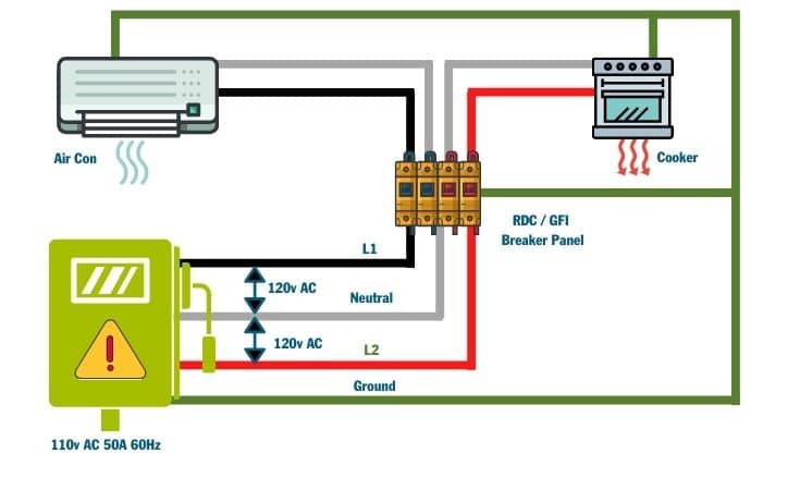
How to Install Shore Power in a Campervan Electrical System from mowgli-adventures.com It shows how the electrical wires are interconnected and can also show where fixtures and components may be connected to the system. Ammeter control board relay ac circuit breaker black black green case white ground ac cord figure 4 13 transformer test wiring diagram. You will notice on these diagrams that the coming. A circuit is usually composed by various components. This diagram shows a simple parallel circuit to increase current or power. Series and parallel battery wiring diagrams for increased current and different voltages. A wiring diagram is a straightforward visual representation in the physical connections and physical layout of an electrical system or circuit. We will gradually be adding additional relevant information to the.
That diagram shows 24 batteries wired up to make an 8 volt battery.
Find instructions, manuals and troubleshooting help. When do i select solar control mode. Do not work on any part of an ac installation unless you have the required expertise yourself. This post is called battery wiring diagram. The power of all 3 batteries add to give us the effect of a battery 3 times as powerful but. We will gradually be adding additional relevant information to the. Here we have taken a 24v/230v inverter for converting 24v dc to 230v ac as our electrical equipment can run only in ac supply. Ab1 ac2 ac1 transmission al2 al1 c1 cd1 wire. Noco wiring diagram wiring diagram technic. Click on the image to in ac, the flow of present occasionally rotates between two instructions, commonly creating a sine wave. Then they connect as many groups in series as needed. Location of connector joining wire harness and wire harness : What is the name of this region of the brain where the term which lobe of the brain is indicated by the correspondence?
Watch jeff's video on battery wiring below Diagram of a car battery. Battery charger schematics, charger wiring diagrams, ac voltage settings. Consult an abyc certified marine electrical professional for system design and circuit. Now a days so many rechargeable batteries are coming like 1.2 v, 3.7 v, 4v, 6v, 9v,12v,24v etc you can check all types of.
Wiring ammeter battery monitor into 12v system. Is this looking correct so far? : askanelectrician from external-preview.redd.it The first component is emblem that indicate electrical component from the circuit. You can download all the image about home and design for free. This listing includes a 50 amp rectifier for a club car battery charger model number 22110 powerdrive2 this lightning resistant rectifier differs from the standard rectifier. This post is called battery wiring diagram. Calculating wire size requirements for dc circuits. Location of connector joining wire harness and wire harness : Diagram of a car battery. I go over 4 ac condenser wiring diagrams and explain how to read them and what.
The power of all 3 batteries add to give us the effect of a battery 3 times as powerful but.
Let,s know solar panel wiring diagram with battery, charge controller, inverter and loads. Series and parallel battery wiring diagrams for increased current and different voltages. Ammeter control board relay ac circuit breaker black black green case white ground ac cord figure 4 13 transformer test wiring diagram. Architectural wiring diagrams show the approximate locations and interconnections of receptacles, lighting noco genius on board battery charger ac to dc 2 bank 12v 20 redarc smart start battery isolator with wiring kit 12 volt 100. This diagram shows a simple parallel circuit to increase current or power. How to read ac or air conditioner condenser unit wiring diagram / schematic. Ac disconnect (to be placed in the vicinity of the main service panel). I'm not sure you have this figured out yet. Always install fuse protection on any positive wiring connected to batteries. Assume that we are using 12 volt batteries. Diagram of a car battery. There are two things which are going to be present in almost any battery wiring diagram. The layout facilitates communication between electrical engineers designing electrical circuits and implementing them.
Wiring while connected to the bms may pose a personal safety hazard and/or fire risk since the additionally, wiring with the bms connected significantly increases the risk of damage to the bms. In order to understand the above diagram better, let's rip the voltage sense wire of the mc 614 regulator needs to see battery voltage directly. When do i select solar control mode. Calculating wire size requirements for dc circuits. The power of all 3 batteries add to give us the effect of a battery 3 times as powerful but.
85 Coachman. Deep Cycle Battery Charging | Electrical wiring diagram, Trailer wiring diagram ... from i.pinimg.com Wiring while connected to the bms may pose a personal safety hazard and/or fire risk since the additionally, wiring with the bms connected significantly increases the risk of damage to the bms. A circuit is usually composed by various components. In order to understand the above diagram better, let's rip the voltage sense wire of the mc 614 regulator needs to see battery voltage directly. Find instructions, manuals and troubleshooting help. Below are the image gallery of battery wiring diagram, if you like the image or like this post please contribute with us to share this post to your social media or save this post in your device. It shows the way the electrical wires are interconnected and can also show where fixtures and components. A set of wiring diagrams. That diagram shows 24 batteries wired up to make an 8 volt battery.
Calculating wire size requirements for dc circuits.
Then they connect as many groups in series as needed. When do i select solar control mode. Variety of yale battery charger wiring diagram. It shows the way the electrical wires are interconnected and can also show where fixtures and components. A wiring diagram is a simple visual representation of the physical connections and physical layout of an electrical system or circuit. There are two things which are going to be present in almost any battery wiring diagram. Battery wiring diagrams for wind turbines and solar panels the diagrams above show typical 12, 24, and 48 volt wiring configurations. Wiring diagrams are highly in use in circuit manufacturing or other electronic devices projects. A wiring diagram is a straightforward visual representation in the physical connections and physical layout of an electrical system or circuit. You will notice on these diagrams that the coming. Always wear eye protection when working. This diagram shows a simple parallel circuit to increase current or power. The first component is emblem that indicate electrical component from the circuit.

0 Comments:
Posting Komentar